 English
 русский
 Español
 عربى
عربى Türk
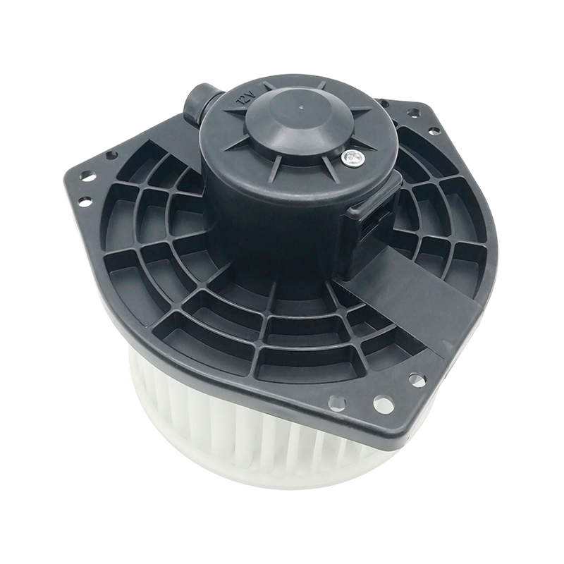
TürkThe JK-66606F is a blower with broad cross-model compatibility, perfectly suited for models such as the Isuzu D-MAX, Nissan Maxima, Sentra A33, and Infiniti I30/I35. It integrates multiple core OEM No...
See DetailsHome / News / Industry News / What Is a Blower Motor Assembly and How Does It Work in a Car HVAC System?
What Is a Blower Motor Assembly and How Does It Work in a Car HVAC System?
Published on 04 10, 2026
Content
- 1 What is a Blower Motor Assembly
- 2 Working Principle of the Blower Motor Assembly
- 3 Blower Motor Assembly Symptoms
- 4 Blower Motor Assembly Not Working Diagnosis
- 5 Blower Motor Assembly Location in Vehicle
- 6 Blower Motor Assembly Wiring Diagram
- 7 Blower Motor Assembly Replacement Steps
- 8 Blower Motor Assembly Maintenance
- 9 Common Misconceptions about Blower Motor Assembly
In modern automotive HVAC (Heating, Ventilation, and Air Conditioning) systems, the Blower Motor Assembly is a critical yet often overlooked component. Whether in hot summer or cold winter conditions, in-cabin air circulation and comfort depend heavily on its stable operation. Many drivers only realize its importance when they experience weak airflow, no airflow, or inconsistent fan speed inside the vehicle.
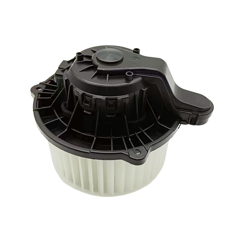
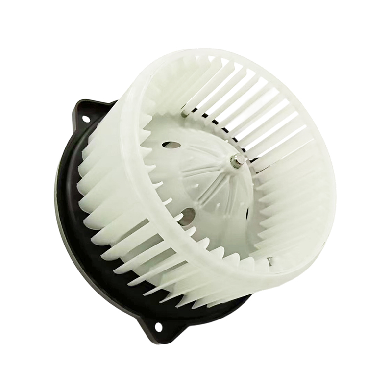
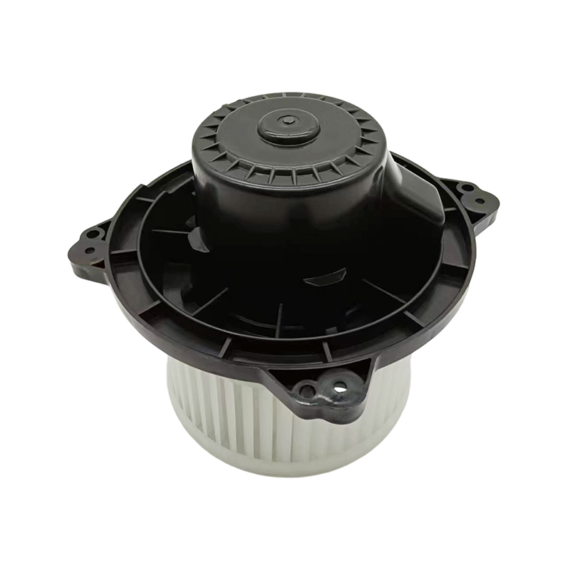
In reality, the Blower Motor Assembly is not just a simple motor. It typically includes the motor unit, fan impeller structure, and sometimes integrated control or mounting components, working closely with the vehicle's HVAC system. Its primary function is to force air through the evaporator or heater core and deliver it into the cabin.
Understanding the structure, operation principles, and common failure symptoms of the Blower Motor Assembly is essential for vehicle maintenance and troubleshooting.
What is a Blower Motor Assembly
Structurally, the Blower Motor Assembly is the air movement core component of an automotive HVAC system. Its main function is to drive airflow so that air can pass through the evaporator or heater core before entering the cabin.
A typical Blower Motor Assembly consists of several key components:
- Electric motor (provides rotational power)
- Fan impeller (generates airflow)
- Housing structure (supports and guides airflow)
- Electrical connector (controls power supply and speed control)
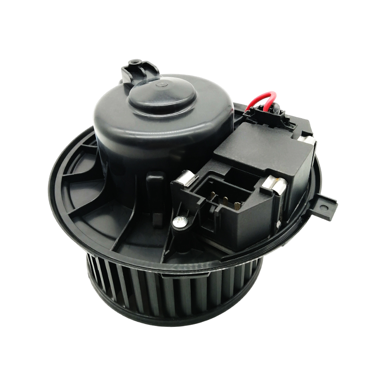
In some vehicles, the Blower Motor Assembly may also include a resistor module or electronic speed control module to achieve multi-speed fan operation.
It is important to distinguish between a blower motor and a Blower Motor Assembly. The blower motor refers only to the motor itself, while the assembly includes a more complete system with mechanical and electrical components.
This integrated design improves installation convenience and enhances airflow efficiency and stability.
Working Principle of the Blower Motor Assembly
To understand the importance of the Blower Motor Assembly, it is necessary to examine how it operates.
When the driver or passenger activates the HVAC system, the control module sends a signal to the Blower Motor Assembly. Electrical current flows into the motor, generating a magnetic field inside the coils, which causes the rotor to spin. At the same time, the fan impeller attached to the shaft rotates at high speed, producing continuous airflow.
Air is then pushed through the cabin air filter, evaporator, or heater core, and finally delivered into the vehicle interior through air vents.
Although the process appears simple, it involves precise coordination between electrical control systems, airflow design, and motor load. Any malfunction in these areas can affect the performance of the Blower Motor Assembly.
Blower Motor Assembly Symptoms
When the Blower Motor Assembly begins to fail, several noticeable symptoms may appear. These signs are often the first indicators of a problem.
One of the most common symptoms is reduced airflow. Even when the HVAC system is set to maximum speed, the air output remains weak. This usually indicates reduced motor speed due to aging or internal resistance increase.
Another common issue is inconsistent fan speed. The system may work on certain speed settings but fail on others. This is often related to problems in the speed control system, especially the resistor module or electronic control circuit.
A complete lack of airflow is another serious symptom. When the Blower Motor Assembly stops working entirely, no air enters the cabin even though the HVAC system is active. This usually indicates power failure or motor damage.
Unusual noises such as buzzing, grinding, or intermittent rattling are also common. These sounds often occur when internal bearings are worn or the impeller is damaged.
Intermittent operation is another key warning sign. The blower may stop working suddenly and resume later, often due to loose wiring connections or thermal protection inside the motor.
Blower Motor Assembly Not Working Diagnosis
Once a potential issue is identified, a systematic diagnostic approach is required to confirm whether the Blower Motor Assembly is faulty.
The first step is to check the vehicle fuse and relay. Since the blower motor is a high-power component, it is usually protected by a dedicated fuse. If the fuse is blown, the system will not operate at all.
Next, it is necessary to measure whether voltage is reaching the motor. If there is no voltage when the system is turned on, the issue may lie in the control switch or wiring rather than the Blower Motor Assembly itself.
If voltage is present but the motor does not operate, the problem is likely internal, such as worn carbon brushes, damaged coils, or a seized bearing.
Another important check is the resistor module or electronic control unit. A faulty module may cause the blower to work only at specific speeds or fail to adjust speed properly.
In some cases, the HVAC control panel itself may fail to send proper signals, preventing the Blower Motor Assembly from responding.
Blower Motor Assembly Location in Vehicle
In most passenger vehicles, the Blower Motor Assembly is located either behind the glove compartment or under the passenger-side dashboard. This positioning allows air to flow efficiently from the filter into the HVAC duct system.
Although layouts vary between vehicle models, the general design principle remains the same: the Blower Motor Assembly is positioned in the middle of the HVAC airflow path to ensure maximum efficiency.
In some compact vehicles, the blower motor assembly may be located near the firewall between the engine compartment and cabin. While this improves space utilization, it may make access more difficult.
A common method to locate the Blower Motor Assembly is to trace backward from the cabin air filter housing, since airflow typically passes directly from the filter into the blower motor area.
Blower Motor Assembly Wiring Diagram
Understanding the electrical system of the Blower Motor Assembly is essential for effective troubleshooting. While wiring layouts vary across vehicles, the basic structure is generally consistent.
The system typically consists of three main circuits:
- Power supply circuit
- Control signal circuit
- Ground circuit
The power supply provides 12V or 24V electricity (depending on the vehicle system) through a fuse and relay to ensure safe operation.
The control circuit is responsible for sending signals from the HVAC control panel or module, allowing the system to adjust speed and operation mode of the Blower Motor Assembly.
The ground circuit completes the electrical loop. Poor grounding can prevent the blower from operating even if voltage is present.
Traditional systems use resistor modules to control fan speed by varying resistance levels. Modern systems increasingly use PWM (Pulse Width Modulation) electronic control modules to regulate motor speed more precisely.
A common symptom of resistor failure is when the blower works only at certain speeds but not others, indicating a partial control failure rather than a motor failure.
Blower Motor Assembly Replacement Steps
When the Blower Motor Assembly is confirmed to be faulty, replacement is typically required. Although procedures vary slightly by vehicle model, the general process is similar.
Before starting, the vehicle power must be disconnected to prevent electrical hazards.
The first step is to remove surrounding components such as the glove box or lower dashboard panel to access the blower motor assembly.
Next, the electrical connector must be carefully disconnected to avoid damaging the locking clip.
Then, the mounting screws securing the Blower Motor Assembly are removed. Typically, there are three to five screws depending on the vehicle design.
After that, the old unit is removed. Due to limited space, slight rotation or tilting may be required for removal.
The new Blower Motor Assembly is then installed, ensuring correct orientation of the impeller and secure mounting to prevent vibration or noise.
Finally, the electrical connection is reattached, and the system is tested by running the HVAC system through all speed settings to confirm proper operation.
Blower Motor Assembly Maintenance
Although the Blower Motor Assembly is generally durable, proper maintenance can significantly extend its service life.
Regular replacement of the cabin air filter is essential. A clogged filter increases airflow resistance and forces the blower motor to work harder, reducing its lifespan.
Avoid prolonged operation at maximum speed, as continuous high load can accelerate wear of internal bearings and carbon brushes.
Moisture protection is also important. Water intrusion or clogged drainage systems may cause corrosion or electrical damage to the blower motor assembly.
Regular inspection for abnormal noise is recommended. Early detection of unusual sounds can prevent more severe damage to the Blower Motor Assembly.
Common Misconceptions about Blower Motor Assembly
There are several common misunderstandings regarding the Blower Motor Assembly in automotive repair.
One frequent misconception is assuming that no airflow automatically means the motor is faulty. In reality, issues often stem from fuses, resistor modules, or control switches rather than the motor itself.
Another misconception is ignoring wiring issues. Many cases of replacement failure occur because electrical faults were not properly diagnosed beforehand.
Additionally, relying solely on voltage testing without considering load conditions can lead to incorrect conclusions, as the Blower Motor Assembly may behave differently under load compared to no-load conditions.
Related products
-
-
A modern air conditioning blower motor for the 2013 and later generation Ford Ranger. Built to exacting original equipment specifications (OEM No. No. 264457, RC.530.136), this motor is designed to me...
See Details -
The JK-66136DZ is a blower assembly with an integrated electronic speed control module, designed specifically for popular Volkswagen Group models. It perfectly replaces the original factory part, ensu...
See Details -
The JK-66144 is a high-quality air conditioning blower specifically designed for Volkswagen Group A0-segment small cars. Its compact design and reliable performance ensure effective interior air circu...
See Details -
This blower, model JK-66423A, is specifically designed for right-hand drive (RHD) vehicles. It's primarily designed for right-hand drive Toyota Corolla models from 2001-2007 and Avensis models from 20...
See Details -
This is a clockwise (CW) blower assembly designed for various Ford models. Designed to adhere strictly to Ford factory standards, it ensures precise installation and compatible electrical connections....
See Details
© 2026 Zhejiang Shuolang Motor Parts Co., Ltd. All Rights Reserved. Custom Automotive Air Conditioning Parts Manufacturer
